HT-powered CW Interface

A keyed piezo beeper, connected to the microphone jack of a HT, appeared feasible as a ready-made MCW generator.

It failed on 3 counts (high pitch, low volume and interrupted carrier) resulting in a very poor-quality signal.

Hence a bit of design effort was called for. The result is the following schematic.

HT-powered CW Interface - Schematic
It's a keyed audio oscillator, with a low part count, working off 4.5V - 1.5mA available at the microphone jack.

Oscillation is obtained using an AC128 (Germanium PNP AF transistor) and an audio transformer with a turns ratio of 1:5.

The 220K and 4.7K trimpots enable adjustment for the desired tone without motorboating.

In the event of the circuit failing to oscillate, connections to one of the transformer windings is reversed.

Connection to the microphone jack is through a shielded cable.

HT-powered CW Interface Board
The prototype was wired on a piece of perforated board with a microswitch serving as the PTT.

The unit was tested/adjusted while monitoring the signal with another rig. 100% modulation, with a clean note, was obtained.

Use of a homebrew electronic keyer precluded the need for a sidetone monitor.

It was an interesting weekend project using parts from the junk box.
______________________________

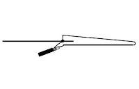
Direction-finding Yagi Beam for 70cm

The PVC pipe/brazing rod construction, used in homebrewing this antenna, is the brainchild of OM Nathan Loucks WB0CMT (A Portable 3-Element 2m Beam - April 1993 QST).

All it requires is a length of 25mm PVC pipe, 2 end caps, 1.6mm brazing rod, a BNC socket, a piece of RG-58U coax and M-Seal epoxy sealant.

70cm Direction-finding Yagi Antenna
Element lengths used:

Driven element: 330mm end-to-end, Director: 305mm, Reflector: 355mm

Element spacing:

Driven element to director: 130mm, Driven element to reflector: 75/85mm.

Conversion of the driven element, from a straight dipole to a half-folded one, was an afterthought to bring the SWR down to less than 1.5:1.

70cm Direction-finding Yagi - detail of driven-element
A length of 18SWG copper wire was used for the conversion.

Related post: Wire Slim Jim for 70cm
______________________________

'Wire Slim Jim' for 70cm

This Slim Jim for 70cm was homebrewed using a length of 18mm diameter thin-walled PVC tube, 20 SWG copper wire, a BNC socket and ‘M-Seal’(epoxy sealant in dual component lump form).

The wire ends and the flange-type BNC socket are secured with self-tapping screws.

Sealing against water ingress is done with M-Seal.

70cm Wire Slim Jim Antenna
A low SWR (less than 1.5:1) was obtained with the feed point at 25mm from the lower end.

This antenna weighs only 90 grams.

Related post: Open Stub J-Pole for 70cm
______________________________

A ¾ λ Ground Plane for 70cm

This antenna is my mast-mounted version of G2BCX OM F.C.Judd's design of a mobile
¾ λ collinear in his 'Two-metre Antenna Handbook'.

It is similar in construction to my ¼ λ Ground Plane for 70cm.

A ¾ λ Ground Plane for 70cm
A SO-239 connector is used.

The driven element, consisting of the ¼ λ lower portion, the ¼ λ hairpin stub and the ½ λ upper portion, is bent from a single brazing rod.

The blue plastic strut gives rigidity to the driven element.

SWR measured lower than 1.5:1 at 435 MHz.

Related post: Another ¼ λ Ground Plane for 70 cm
______________________________